Burner assembly #1
Raku burner assembly #1 4400 m- 15 kW/0,6 Bar
The Raku propane burner assembly #1 4400 - 15 kW/0,6 Bar is the standard burner set we deliver with our Kilns Type 160 and 260.

Raku assembly #1
Tech spec. excl. thermal safety
| Gas pressure | Burner capacity | Gas consumption |
| Bar | kW | kg/h |
| 0,2 | 9 | 0,6 |
| 0,4 | 13 | 0,9 |
| 0,6 | 15 | 1,1 |
| 0,8 | 18 | 1,3 |
The burner set consist of:
Adjustable pressure regulator
The pressure regulator reduces the gas pressure as it is in the gas tank to a suitable pressure for the burner.
Because the pressure regulator is adjustable we can control the gas pressure given to the burner and with it the firing of the kiln.
The pressure regulator is connected to the gas tank with a Shell coupling nut (Wrench Nr.30). This nut has "left" female threat which common practice with gas connections.
Check every time you connect the pressure regulator that the gasket inside the nut is in position, even when the tank connection itself is also fitted with a gasket. The latter one does not replace the gasket of the pressure regulator.
After you have tighten the coupling nut by hand you can give some additional torque with the wrench but there is no need for a lot force here. Tight is tight.
The normal operating pressure area of the burner lies between 0 and 0,8 bar with a max. of 1,5 bar.
It is recommended to apply a bit of silicon spray every now and then to the adjusting lever to keep it smooth going.
Propane hose
Length of the hose is approx. 3m. and it is fitted with a coupling nut (Wrench Nr.19) to the pressure regulator. Also here left threat is applied so loosening and tightening goes exactly in the other direction as you are used to. This connection has no gasket but has to be sealed by torque. Tighten the nut with your hand and apply additional torque with the wrench. But do not overdo this. Tight is tight
Check before firing the condition of the hose. If you see changes in colour or cracks in the hose then you need to replace it.
The year of manufacturing is printed on the hose. In general recommendation is to replace hoses older than 2 years.
Price of the spare hose is to be found in Price list Nr. 3 Kiln Building.
Shut off valve
The gas flow to the burner can be shut off with this valve.
-Is the grip of the valve positioned in the direction of the gas flow then the valve is opened.
-With the grip at a 900 angle to the flow direction the valve is closed.
The valve is not intended to regulate the amount of gas to the burner by having it half or partly opened. Regulating the burner is only done with the pressure regulator.
Between two firing sessions it is enough to have just this valve closed. The valve of the gas tank can stay opened. Of coarse before disconnecting the burner the tank valve should always be closed.
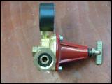
Pressure regulator
Ventury burner
The propane burner consists of (1) gas orifice, (2) cast iron ventury tube and (3) ceramic flame head.
(1) Orifice
The gas orifice needs to be clean. Should the small gas bore get polluted or partly blocked by pollution than this will certainly has a negative effect on the burner performance.
When you have removed the orifice from the shut off valve than you need to apply seal tape the close the connection with the shut off valve. With the threat connection between the orifice and the ventury tube this is not necessary
(2) Venturytube
Due to the shape of the ventury tube, air will be drawn towards the propane flame as soon as propane gas is being injected by the orifice. By gradually closing the air intake openings at the end of the ventury tube near de shut off valve the ratio between gas and air can be influenced such that a reductive environment will occur in the kiln.
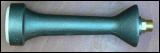
(3) Ceramic flame head
The ceramic flame head is fragile. Make sure that it does not hit the ground while unwinding and mounting the burner assembly to the gas tank. Replace the flame head with it is broken.
Propane burner #1
(C) 2005 - All rights reserved